
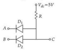
Two junction diodes and are connected as shown in the figure. and are input signals and is the output. The given circuit will function as a _.
- A
NOR Gate
- B
NAND Gate
- C
AND Gate
- D
OR Gate
Two junction diodes and are connected as shown in the figure. and are input signals and is the output. The given circuit will function as a _.
NOR Gate
NAND Gate
AND Gate
OR Gate
Correct answer:C
Standard Method
Given: Two junction diodes and are connected with a pull-up resistor to . Inputs are and , and output is .
Find: Which logic gate this circuit represents.
Concept: In diode logic, a forward-biased diode conducts and can pull the output node LOW, while a reverse-biased diode does not conduct.
Step 1: Understand the circuit A pull-up resistor connects the output node to . The diodes are oriented such that a LOW input can pull the output LOW.
Step 2: Truth table analysis
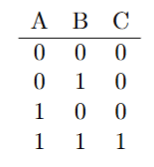
Explanation: If either or , the corresponding diode conducts and pulls LOW. Only when both and , both diodes are reverse-biased and the pull-up resistor makes HIGH.
Conclusion: The output is HIGH only when both inputs are HIGH. Therefore, the correct option is C, that is, AND Gate.
Confusing pull-up resistor behavior with pull-down resistor behavior. Here the resistor pulls the output HIGH by default, so a conducting diode pulls it LOW; do not assume the same logic as a pull-down arrangement.
Identifying the gate only from the presence of diodes without checking their orientation. The diode direction determines whether a LOW input or a HIGH input controls the output, so the truth table must be verified.
Get unlimited AI-adaptive practice, mastery tracking, and an AI tutor that explains every step — free to start.