MCQEasyJEE 2023Logic Gates

JEE Physics 2023 Question with Solution

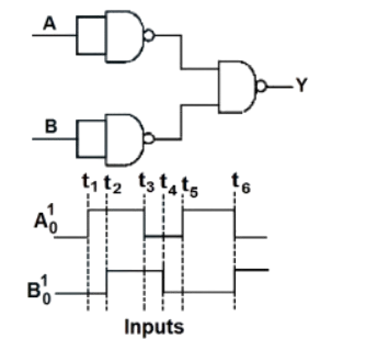
The output waveform of the given logical circuit for the following inputs AA and BB is shown below:

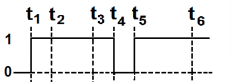
Logical circuit made of NAND gates with inputs A and B, producing output Y, along with input timing waveforms marked t1, t2, t3, t4, t5 and t6.
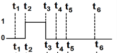
  • A
    Output waveform option A with time markers t1, t2, t3, t4, t5 and t6, showing a high level only between early time markers and low elsewhere.
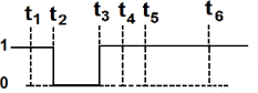
  • B
    Output waveform option B with time markers t1, t2, t3, t4, t5 and t6, showing the signal high initially and then low for the remaining interval.
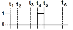
  • C
    Output waveform option C with time markers t1, t2, t3, t4, t5 and t6, showing two separate high pulses at the beginning and around t4 to t5.
  • D
    Output waveform option D with time markers t1, t2, t3, t4, t5 and t6, showing high output in the first interval, low in the middle, and high again afterward.

Answer

Correct answer:D

Step-by-step solution

Standard Method

Given: The logical circuit is formed using NAND gates and the input waveforms of AA and BB are provided.

Find: The correct output waveform YY.

Given circuit represent XOR.

For an XOR gate,

Y=ABY = A \oplus B

The output is 11 when the inputs are different and 00 when the inputs are same.

Its truth table is

ABY000011101110\begin{array}{c|c|c} A & B & Y \\ \hline 0 & 0 & 0 \\ 0 & 1 & 1 \\ 1 & 0 & 1 \\ 1 & 1 & 0 \end{array}

So the waveform must be high exactly in those time intervals where ABA \ne B.

Therefore, the correct option is D.

Truth table of XOR gate with columns A, B and Y showing outputs 0, 1, 1, 0 for input pairs 00, 01, 10 and 11 respectively.

Gate Analysis

Given: The circuit uses NAND gates with inputs AA and BB.

Find: Which option gives the output waveform YY.

The circuit provided in the image represents an XOR gate. Using NAND-gate construction:

NAND1=AB\text{NAND1} = \overline{A \cdot B} NAND3=AAB\text{NAND3} = \overline{A \cdot \overline{A \cdot B}} NAND4=BAB\text{NAND4} = \overline{B \cdot \overline{A \cdot B}} Y=(AABBAB)Y = \overline{\left(\overline{A \cdot \overline{A \cdot B}} \cdot \overline{B \cdot \overline{A \cdot B}}\right)}

This simplifies to

Y=ABY = A \oplus B

Now use the XOR truth table:

ABY000011101110\begin{array}{c|c|c} A & B & Y \\ \hline 0 & 0 & 0 \\ 0 & 1 & 1 \\ 1 & 0 & 1 \\ 1 & 1 & 0 \end{array}

Hence YY is high whenever the two input waveforms differ and low whenever they are equal.

Therefore, the output waveform matches Option D.

Common mistakes

  • Mistake: Treating the circuit as an OR gate. Why it is wrong: an OR gate gives output 11 for A=1,B=1A = 1, B = 1, but XOR gives 00 there. What to do instead: first identify the NAND-gate combination as an XOR realization.

  • Mistake: Comparing only one input waveform at a time. Why it is wrong: the output depends on both AA and BB simultaneously. What to do instead: mark intervals where the two inputs are equal and unequal, then assign XOR output accordingly.

  • Mistake: Confusing NAND output with the final circuit output. Why it is wrong: intermediate NAND outputs do not directly give YY. What to do instead: analyze the complete gate network or use the recognized standard XOR construction.

Practice more Logic Gates questions

Get unlimited AI-adaptive practice, mastery tracking, and an AI tutor that explains every step — free to start.

Related questions