
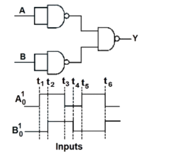
The output waveform of the given logical circuit for the following inputs and is shown below:
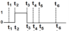
- A
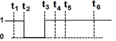
- B
- C
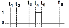
- D
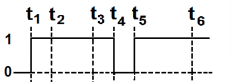
The output waveform of the given logical circuit for the following inputs and is shown below:
Correct answer:D
Standard Method
Given: The logical circuit is formed using NAND gates and the input waveforms of and are provided.
Find: The correct output waveform .
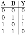
Given circuit represent XOR.
For an XOR gate,
The output is when the inputs are different and when the inputs are same.
Its truth table is
So the waveform must be high exactly in those time intervals where .
Therefore, the correct option is D.
Gate Analysis
Given: The circuit uses NAND gates with inputs and .
Find: Which option gives the output waveform .
The circuit provided in the image represents an XOR gate. Using NAND-gate construction:
This simplifies to
Now use the XOR truth table:
Hence is high whenever the two input waveforms differ and low whenever they are equal.
Therefore, the output waveform matches Option D.
Mistake: Treating the circuit as an OR gate. Why it is wrong: an OR gate gives output for , but XOR gives there. What to do instead: first identify the NAND-gate combination as an XOR realization.
Mistake: Comparing only one input waveform at a time. Why it is wrong: the output depends on both and simultaneously. What to do instead: mark intervals where the two inputs are equal and unequal, then assign XOR output accordingly.
Mistake: Confusing NAND output with the final circuit output. Why it is wrong: intermediate NAND outputs do not directly give . What to do instead: analyze the complete gate network or use the recognized standard XOR construction.
Get unlimited AI-adaptive practice, mastery tracking, and an AI tutor that explains every step — free to start.