
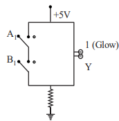
The logic gate equivalent to the given circuit diagram is:
- A
OR
- B
NAND
- C
NOR
- D
AND
The logic gate equivalent to the given circuit diagram is:
OR
NAND
NOR
AND
Correct answer:B
Standard Method
Given: A circuit diagram with two inputs and and output .
Find: The logic gate represented by the circuit.
The circuit diagram represents a NAND gate. Let’s analyze the behavior of the circuit:
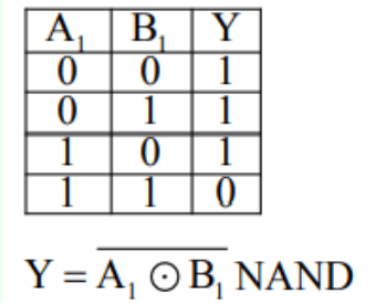
This behavior matches the truth table of a NAND gate:
Thus, the circuit corresponds to the logic of a NAND gate, with the output given by:
Therefore, the correct option is B.
Truth Table Identification
Given: The switch circuit output glows for most input combinations.
Find: Which logic gate matches the output pattern.
Check the output states directly:
A gate whose output is only when both inputs are is NAND.
Therefore, the correct option is B.
Confusing NAND with AND. In an AND gate, output is only when both inputs are , but here the output becomes for that case. Compare the full truth table before choosing.
Ignoring the meaning of the glowing bulb. Here, bulb glow corresponds to output and no glow corresponds to output . Reversing this interpretation leads to the wrong gate.
Looking only at the circuit shape instead of the switching behavior. For such questions, determine output for all input combinations and then match with the standard truth table.
Get unlimited AI-adaptive practice, mastery tracking, and an AI tutor that explains every step — free to start.