
In the given circuit the value of is _____.
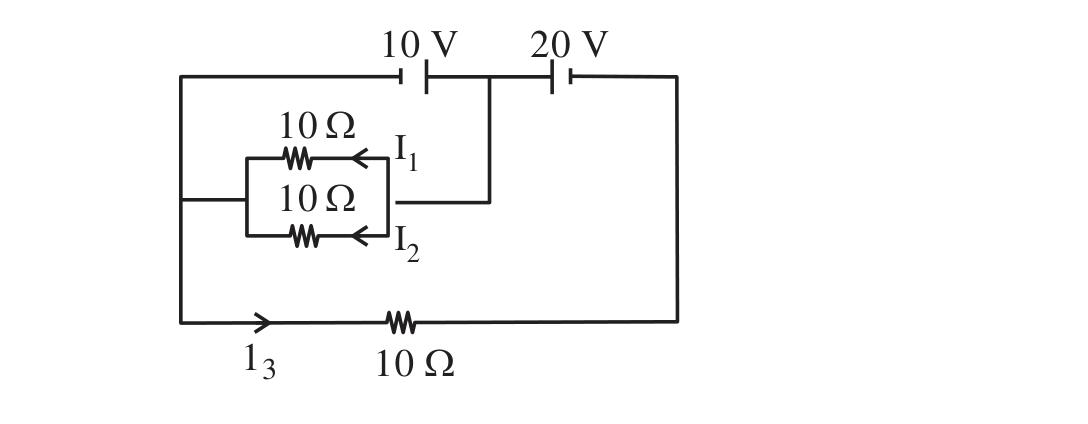
In the given circuit the value of is _____.
Correct answer:2
Standard Method
Given: The circuit has three resistors of each, with currents , , and as marked.
Find: The value of .
From the extracted solution, the currents are taken as
and
Now substitute these values into the required expression:
Therefore, the value of the given expression is .
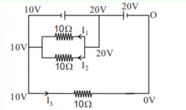
Using node potentials from the figure
Given: The annotated figure indicates the left side is at , the middle junction is at , and the right side is at .
Find: .
Each of the two inner resistors of is connected between the node and the node, so the potential difference across each is . Hence,
The bottom resistor is connected between and , so
Now evaluate the ratio:
The source HTML also contains an inconsistent intermediate value , but its final conclusion and the second approach both give , which is the accepted answer.
Therefore, the correct numerical value is .
Using the battery values directly without first identifying the node potentials is incorrect. The current in each resistor depends on the potential difference across that resistor, so first read or determine the node voltages and then apply .
Adding source voltages and resistor voltages from unrelated branches in a single KVL equation is wrong. Write loop equations only for a complete closed loop, or use node potentials when the circuit is easier to read that way.
Ignoring the absolute value in can lead to a sign error. Even if a chosen current direction gives a negative ratio, the required final value must be non-negative.
Get unlimited AI-adaptive practice, mastery tracking, and an AI tutor that explains every step — free to start.