MCQEasyJEE Main 2023 · 6 April, Shift 2Ohm's Law Verification

Physics Question from JEE Main 2023 · 6 April, Shift 2

A student is provided with a variable voltage source VV, a test resistor RT=10ΩR_T = 10 \, \Omega, two identical galvanometers G1G_1 and G2G_2, and two additional resistors, R1=10MΩR_1 = 10M\Omega and R2=0.001ΩR_2 = 0.001\Omega. For conducting an experiment to verify ohm’s law, the most suitable circuit is:
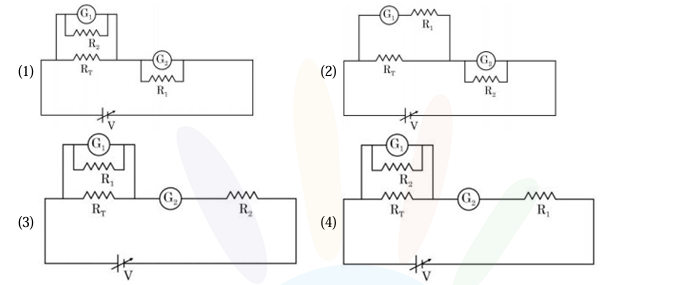
Four circuits labelled (1) to (4), each with a variable source V driving a loop containing the test resistor R_T. (1): G1 in parallel with R2 across R_T, and G2 in parallel with R1 in the loop. (2): G1 in series with R1 across R_T, and G2 in parallel with R2 in the loop. (3): G1 in parallel with R1 across R_T, and G2 in series with R2 in the loop. (4): G1 in parallel with R2 across R_T, and G2 in series with R1 in the loop.
  • A

    Circuit (1)(1)G1G_1 shunted by R2R_2, that combination connected across RTR_T; G2G_2 shunted by R1R_1, placed in series in the main loop.

  • B

    Circuit (2)(2)G1G_1 in series with R1R_1, that branch connected across RTR_T; G2G_2 shunted by R2R_2, placed in series in the main loop.

  • C

    Circuit (3)(3)G1G_1 shunted by R1R_1, that combination connected across RTR_T; G2G_2 in series with R2R_2, placed in series in the main loop.

  • D

    Circuit (4)(4)G1G_1 shunted by R2R_2, that combination connected across RTR_T; G2G_2 in series with R1R_1, placed in series in the main loop.

Answer & step-by-step solution

Sign in to reveal the correct answer, the full step-by-step solution, and the common mistakes for this question.

Practice more Ohm's Law Verification questions

Get unlimited AI-adaptive practice, mastery tracking, and an AI tutor that explains every step - free to start.