
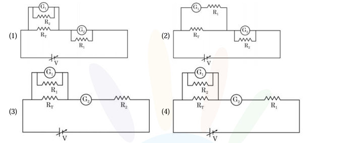
A student is provided with a variable voltage source , a test resistor , two identical galvanometers and , and two additional resistors, and . For conducting an experiment to verify ohm’s law, the most suitable circuit is:
- A
(1)
- B
(2)
- C
(3)
- D
(4)
A student is provided with a variable voltage source , a test resistor , two identical galvanometers and , and two additional resistors, and . For conducting an experiment to verify ohm’s law, the most suitable circuit is:
(1)
(2)
(3)
(4)
Correct answer:D
Standard Method
Given: A variable voltage source , test resistor , two identical galvanometers and , and resistors and .
Find: The most suitable circuit for verifying Ohm’s law.
To verify Ohm’s law, the ammeter must be connected in series with the test resistor and the voltmeter must be connected in parallel across it.
A galvanometer is converted into an ammeter by connecting a very small shunt resistance in parallel. Here, is very small, so it should be used as the shunt.
A galvanometer is converted into a voltmeter by connecting a very large resistance in series. Here, is very large, so it should be used in series with the galvanometer.
Thus, the correct circuit is the one in which:
All these conditions are satisfied by option (4).
Therefore, the correct option is D.
Concept Check
Given: The two added resistors are and .
Find: Which circuit uses the galvanometers correctly.
The required instrument placements are:
So, for the galvanometers:
Now compare the circuits. The suitable one is the circuit where the voltmeter combination is across and the ammeter combination is in series with the circuit.
Hence, the correct choice is option (4), that is D.
Using the large resistance as a shunt for making an ammeter. This is wrong because an ammeter must have very low resistance. Use the very small resistance in parallel with the galvanometer instead.
Connecting the voltmeter combination in series with the test resistor. This is wrong because a voltmeter must measure potential difference across the resistor. Connect it in parallel across instead.
Connecting the ammeter combination in parallel across . This is wrong because an ammeter must measure the current through the resistor. Place it in series in the main circuit instead.
Get unlimited AI-adaptive practice, mastery tracking, and an AI tutor that explains every step — free to start.